

Do You Have Service Questions or Need Spare Parts?


Components
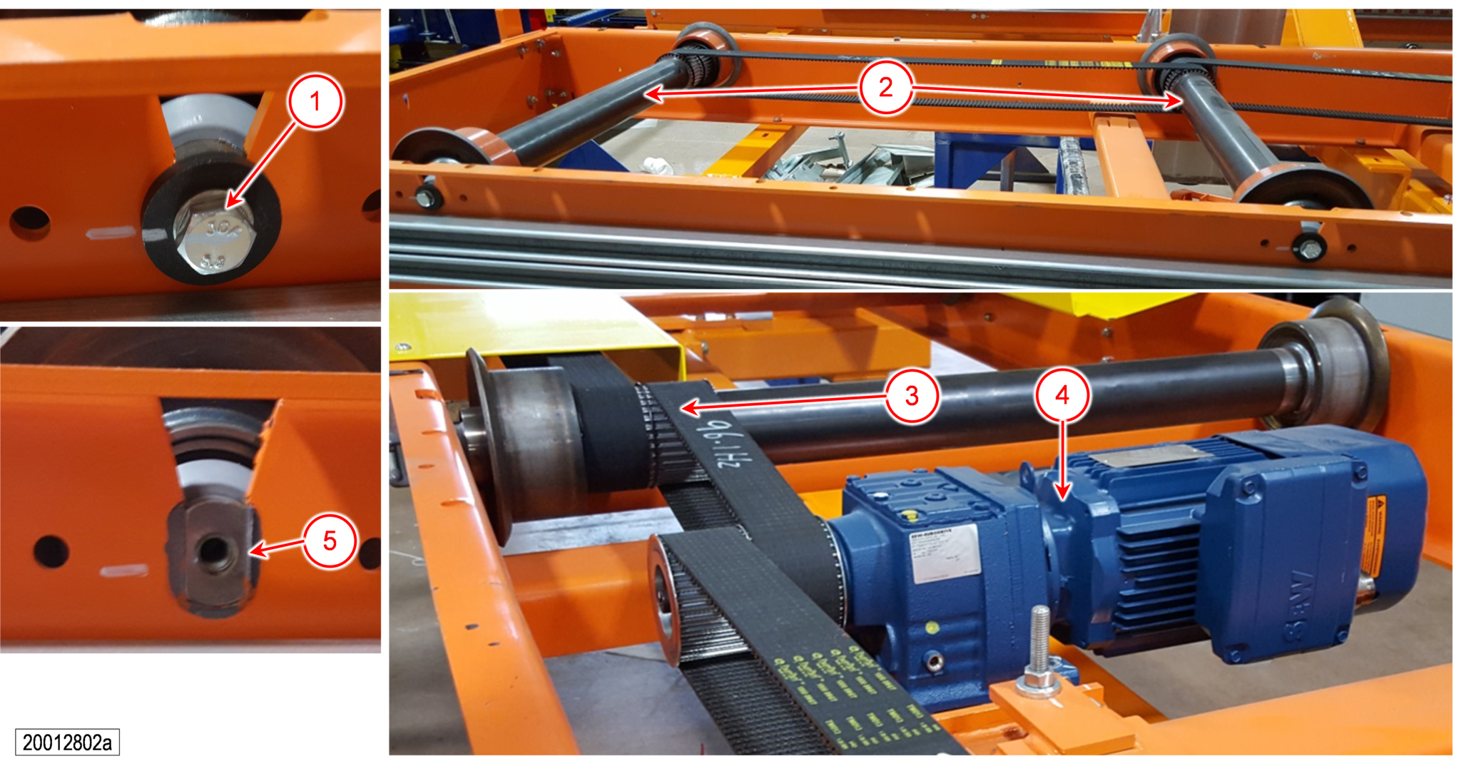
| The typical roller table module consists of the following components: 1. Side frames 2. Gearmotor 3. IDC 4. Carrying rollers 5. Support with adjustable feet 6. Toothed belts 7. Drive belts 8. Brake Lever for motor brake 9. Lead in blocks 10. Proximity switches 11. TEE brackets 12. Dashboard |
 |
Preventive Maintenance
|
Please Note:
|
Fill Gear Oil Table
| Part Description | Type of Gearing | Type of Oil | Mfgr Type | Viscosity/ Grade |
| SEW Drive Units | Helical-Bevel | Synthetic | Shell Omala S4-GX220 | ISO VG 220 |
Recommended Grease Lubricant Table
| Application Field | Type/Grade | Recommended Brands |
| Generic Bearings: Pillow, Flange, Roller | All-purpose/NLGI 2 | Mobil Mobilux EP2 or Shell Alvania EP 2 |
Daily Checks
Each day you should walk around the system and look for the following:
- Obvious signs of damage to the equipment.
- Damage or noticeable wear on the carrying and guide rollers.
- Signs of oil leaks on the equipment or on the floor below any gearbox.
- If you notice any of the above issues, perform the necessary maintenance or repair immediately.
Preventive Maintenance Schedule

| Interval (In Months) | Item Number | Item Name | Required Operation | Description |
| 3 |
1 |
Carrying Roller | Inspection |
Check rollers for bearing clearance, damage, and wear. Abrasion should not exceed 5 mm on diameter (minimum diameter is 120 mm), unevenness at the surface maximum 3 mm. |
| 3 | 2 | Motor Drive Pulley | Inspection | Check secure mounting on drive shaft. |
| 3 | 3 | Drive Toothed Belt | Inspection |
Check for sufficient tension, if necessary, replace belt Check for excessive fraying on belt edges and for broken teeth. |
| 3 | 4 | Driven Toothed Belt(s) | Inspection |
Index the lift. Check that belts run freely and without excessive noise Check for excessive fraying on belt edges and for any exposed reinforcing wires. |
| 6 | 5 | Gearmotor | Inspection |
Check gearmotor for excessive noise. Remove the oil level plug to check the level of oil. See Fill Gear Oil Table for recommended lubricants. |
| 36 | 5 | Gearmotor | Lubrication | Replace gearmotor oil. Depending on operating conditions, oil change interval may be shorter. |
Maintenance
|
Please Note:
|
Replace Carrying Roller
- Remove and lock out power to the power roller table using your plant’s procedures.
- Remove cover with socket head cap screw and hex nut. In order to replace a toothed belt or a carrying roller, the appropriate roller must be disassembled beginning at the motor side.
- Remove the hex head screws [1] holding the shafts [2] on both sides of the carrying roller.
- If carrying roller clamps between side frames, use suitable means (e.g., screw clamp) to force the side frames slightly apart, so that the carrying roller can be withdrawn upwards. Don’t bend the side frames more than necessary (max. 2 mm)
- Thread the new carrying roller through the two toothed belts [3] so that the belts are on the pulley.
- The assembly begins at the motor side. All carrying rollers are bolted only slightly with the toothed belt. Now the carrying roller at the front side must be pressed outwards as far as possible and firmly screwed. In the next step all further carrying rollers are firmly screwed from the outside inwards in such a way that the belt tension becomes as high as possible. The belt tension of the two drive-toothed belts can be optimized by moving the motor [4].
- Turn the roller so that the rod end [5] fits into the slot on the frame.
- Retighten all hex head screws firmly.
- Assemble cover again with hex socket head cap screw.
- Restore power to the pivot/turn table and test for proper operation.
Replace Tooth Belt between Carrying Rollers
- Remove and lock out power to the power roller table using your plant’s procedures.
- Remove cover with Socket head cap screw and hex nut.
- In order to replace a toothed belt, all carrying rollers must be disassembled that are mounted at the respective motor side. First remove the outer carrying roller of the dashboard and carry on up to the carrying roller beside the motor.
- Remove the hex head screws holding the rod on both sides [1] of the carrying roller [2].
- If carrying roller clamps between side frames, use suitable means (e.g., screw clamp) to force the side frames slightly apart, so that the carrying roller can be withdrawn upwards. Don’t bend the side frames more than necessary (max. 2 mm)
- Install the new toothed belt [3] around the carrying rollers [2].
- The assembly begins at the motor side. All carrying rollers are bolted only slightly with the toothed belt. Now the carrying roller at the front side must be pressed outwards as far as possible and firmly screwed. In the next step all further carrying rollers are firmly screwed from the outside inwards in such a way that the belt tension becomes as high as possible. The belt tension of the two drive-toothed belts can be optimized by moving the motor [4].
- Turn the rod end [5] to fit into the slot in the frame and install their screws.
- Retighten all hex head screws firmly. Take great care that there is contact between the flange bearing and the side frames.
- Assemble cover again with hex socket head cap screw.
- Restore power to the power roller table and test for proper operation.

Replace Gearmotor
- Remove and lock out power to the power roller table using your plant’s procedures.
- Remove protection cover.
- Loosen screws [2] at one side of the motor
- Remove hex-head screws [1].
- Hoist gearmotor [3] and remove tooth belts [4] from pulley.
- Dismantle head screw joint [5]
- Remove pulley [6] with pin.
- Mount pulley [6] at new gearmotor [3].
- Install pulley [6] locked with new split pin.
- Fit tooth belt on pulley.
- Setting gearmotor [3], adjust the tooth belt tension with hex-head screws [2] and tighten gearmotor with hex head screws [1]. Take care, that motor is exactly at right angle with the chain drive.
- Restore power to the power roller table and test for proper operation.
Replace Drive Belt Pulley from Gearmotor
- Remove and lock out power to the power roller table using your plant’s procedures.
- Remove cover with hex socket head cap screw.
- Remove hex head screws [1].
- Dismantle hex head screws [2] only from one side of the gearmotor.
- Hoist gearmotor [3] and remove tooth belts [4] from pulley.
- Dismantle screw joint [5].
- Remove washer with pin
- Remove pulley [6].
- Mount new pulley [6] at gear-motor [3], fit with hex socket head cap screw (M10).
- Install washer locked with new split pin.
- Fit toothed belt [4] and hex head screw on gearmotor slightly [1] (M16).
- Setting gearmotor [3], adjust the tooth belt tension with her head screws [2] (M16) and tighten gearmotor must exactly at right angle with the belts, both belts must be equally tensioned. (See tension belt chart).
- Assemble cover again with hex socket head cap screw.
- Restore power to the power roller table and test for proper operation.

Check for Sufficient Belt Tension
- Remove and lock out power to the power roller table using your plant’s procedures.
- Remove cover with hex socket head cap screw.
- For inspection equipment use belt tension measuring instrument “TENSION METER”
- Hit the belt [1] with a metallic article (spanner or similar) to cause the belt to vibrate.
- Refer to belt tension-measuring instrument operating manual for the frequency checking procedure. Vibrating frequency refer to module belt chart.
- If a belt cannot become correctly tightened (<10Hz), then the belt is to be replaced.
- If the tension of belt is too high, and/or cannot be adjusted, then the belt should be replaced.
- Restore power to the power roller table and test for proper operation.